Internal Forces on Structures :
Internal forces refer to the forces that act within a system or structure, as opposed to external forces, which are applied from outside the system. These forces are responsible for maintaining the integrity and stability of the material or object under consideration.


In the context of mechanical engineering or physics, internal forces typically include:
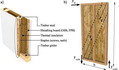
Tensile Forces: These forces stretch or pull materials. In a structural element, they act to elongate the material.
Compressive Forces: These forces push or compress materials, shortening or squeezing them.
Shear Forces: These forces act parallel to the surface of a material, causing it to deform by sliding parts of the material relative to each other.
Bending Moment:
A bending moment is a measure of the internal force that causes a structural element (such as a beam) to bend when subjected to external loads or forces. It is a result of the external forces and moments applied to the beam, and it varies along the length of the beam.
- The bending moment at any point along a beam is the sum of the moments (forces multiplied by distance) about that point. It can either cause tension (on one side of the beam) and compression (on the opposite side) in the material.
- In a positive bending moment (clockwise moment when viewed from one end), the top of the beam is in compression and the bottom is in tension. In a negative bending moment (counterclockwise), the top is in tension and the bottom is in compression.
Bending moments are critical in the design of beams, as they determine the stresses within the material, and excessive bending can lead to failure through cracking or material rupture.
Twisting (Torsion):
Twisting or torsion refers to the internal response of a structural element, typically a shaft or a cylinder, when it is subjected to a torque or a rotational force. The force tends to twist one end of the object in relation to the other.
- When a torque is applied to an object, it creates shear stresses within the material, distributed along its cross-section. These shear stresses are what resist the twisting motion.
- The twisting is typically characterized by the torsional moment (also known as torque) applied at the ends of the object. This results in a shear strain and can cause the material to twist around its longitudinal axis.
Buckling of a Column is a structural instability phenomenon that occurs when a column or strut subjected to compressive axial loads deforms significantly, leading to failure. Unlike materials that fail by fracture or yielding under stress, buckling is a failure mode dominated by geometry and the type of loading.

Key Points about Buckling:
Cause of Buckling: Buckling typically occurs when the compressive load applied to the column exceeds a critical value, called the critical load or buckling load. When this load is exceeded, the column can deform laterally, creating a curve or bending. This behavior is mostly observed in slender (long and thin) columns, which are more prone to buckling.
Critical Buckling Load: The load at which buckling begins is determined by the column's geometry (length, cross-sectional area, moment of inertia) and the material properties (Young's modulus and yield strength). For a column with pinned ends, the Euler's buckling load can be expressed as:
Where:
- = critical buckling load
- = modulus of elasticity (Young’s modulus)
- = moment of inertia of the column’s cross-section
- = length of the column
- = column effective length factor (depends on boundary conditions)
Types of Buckling:
- Elastic Buckling: Occurs when the stress in the material remains below the yield strength, and the column recovers its shape when the load is removed.
- Inelastic Buckling: Occurs when the stress exceeds the yield point of the material, leading to permanent deformation even if the load is reduced.
Factors Affecting Buckling:
- Column Length: Longer columns are more likely to buckle compared to shorter ones.
- Column Cross-Section: Columns with smaller moments of inertia or weak shapes (e.g., thin-walled sections) are more prone to buckling.
- Boundary Conditions: Columns with fixed ends can withstand higher loads before buckling compared to columns with pinned or free ends. The type of boundary condition affects the effective length factor () in the buckling load equation.
- Material Properties: The higher the material's modulus of elasticity (stiffness), the less likely it is to buckle.
Mode of Buckling: When a column buckles, it doesn't collapse straight down; rather, it bends sideways. The mode of buckling can vary, typically leading to a sinusoidal deflection shape.
Prevention and Design Considerations:
- To prevent buckling, columns must be designed to carry loads safely without reaching the critical load. This involves selecting appropriate materials, lengths, and cross-sectional shapes.
- Slenderness ratio: The ratio of the column's effective length to its radius of gyration () helps determine the likelihood of buckling. A higher slenderness ratio indicates a higher risk of buckling.
Post-Buckling Behavior: After buckling, a column may exhibit large deformations or go into a state where it cannot carry additional load without significant failure
.jpg)
Comments
Post a Comment